Calculating Worm Gear Dimensions
An application of Machinery's Handbook equations using Excel to calculate worm gear dimensions for astrophotography tracking mounts.

This is the first post of what will hopefully become a three-part series on machining worm gears for equatorial telescope mounts. Enjoy :).
Background
Most German equatorial mounts (aka GEMs) for astrophotography rely on worm gears to drive the main motion of the mount.
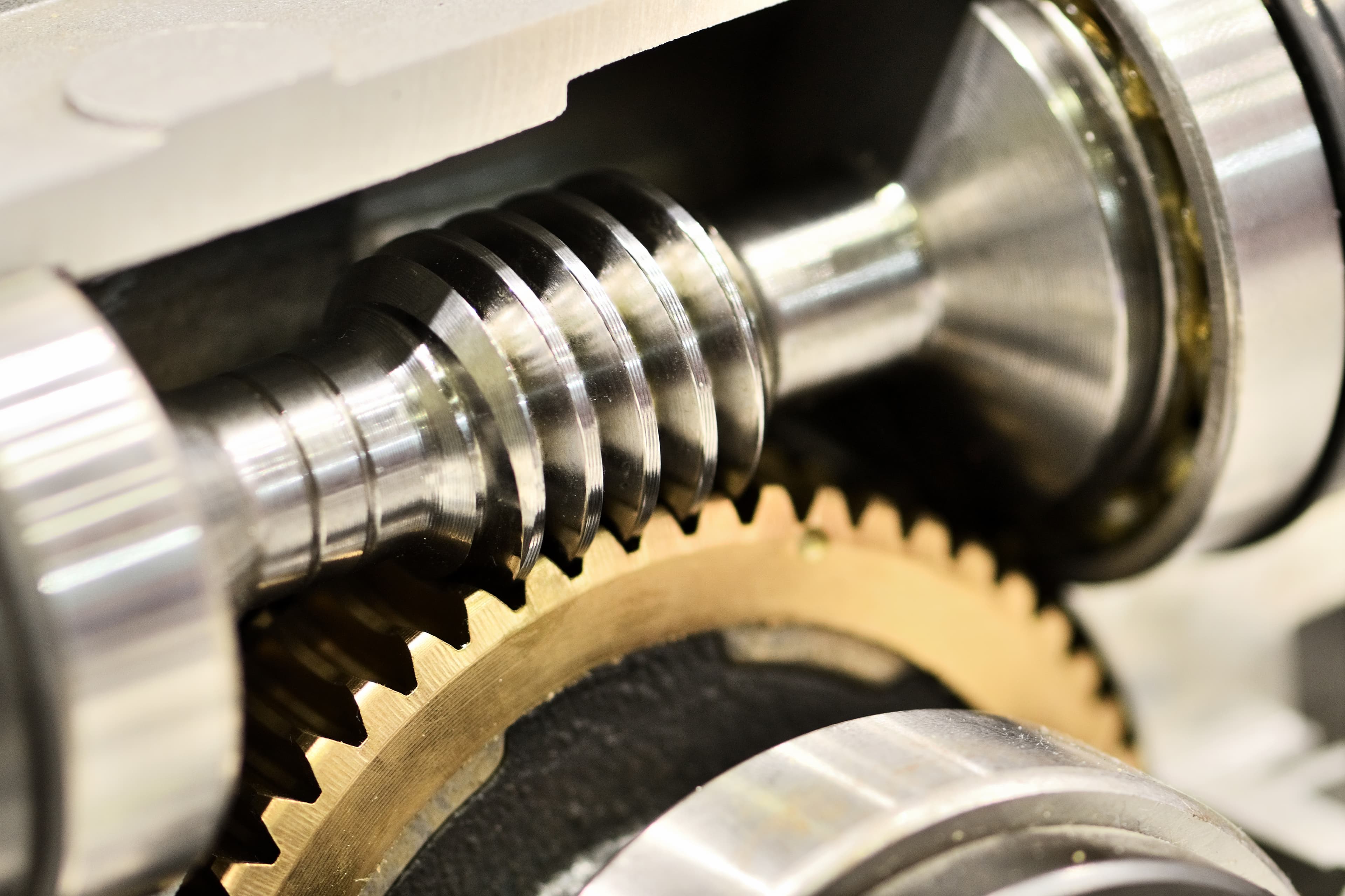
A set of worm gears is comprised of two parts: 1) the worm, which is essentially a threaded cylinder, and 2) the worm gear itself, which is a disc with teeth carved into it that match the worm's thread profile. Sometimes, worm gears are also called worm wheels.

Worm gears hold numerous advantages over other, more straightforward, gear mechanisms. For one, they are self-locking: torque on the worm gear won't make the worm spin because its helical teeth are nearly orthogonal to the direction the gear rotates.
Additionally, worm gears have almost no backlash (dead space where the gear and worm aren't actually touching each other) if machined properly, which allows for autoguiding (tiny, real-time adjustments while tracking with software like PHD2).
Fabrication Approach
Although it's ideal to machine worm gears using a custom hob made with a lathe that supports auto-feed, there's an alternate (and arguably easier) method to make a set of high quality worm gears for astrophotography when you might not have enough resources available. You can simply use a tap as a ready-made hob from which to carve a worm wheel; then, a section of matching threaded rod can be used as the worm.
I've written two other blog posts documenting how I machined the worm and worm gear that I used for my own equatorial mount.
Resources
Machinery's Handbook
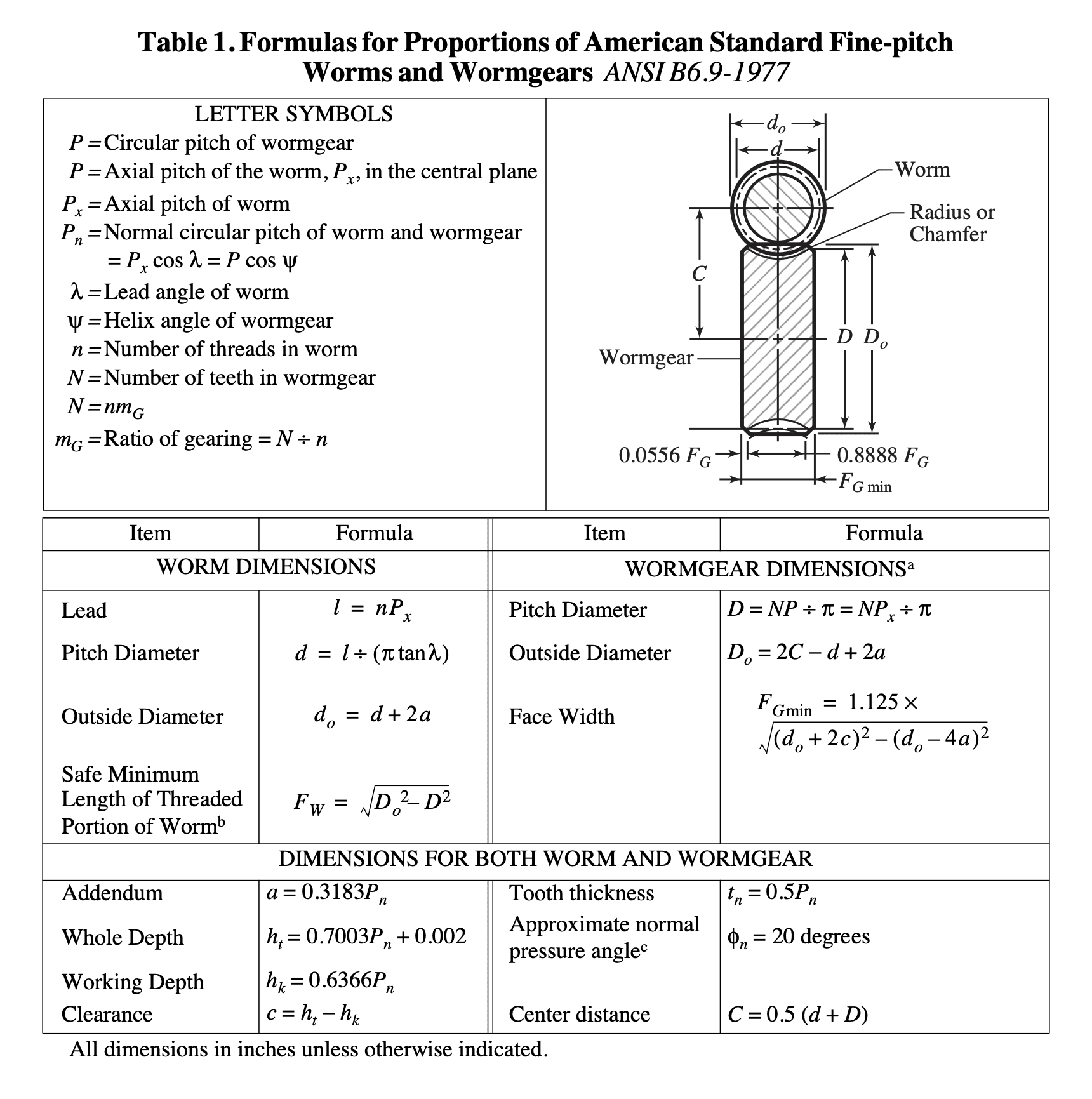
For my equatorial mount build, I chose to use a 3/4"-16 tap (16 TPI is very close to a 1.5mm pitch - a standard for worm gears). While researching how to fabricate my worm wheel after selecting a tap, I stumbled across a page in the Machinery's Handbook with numerous equations that were an immeasurable help. The most useful of these was an equation for whole depth, which is precisely how deep to carve into the gear blank during the hobbing process.

Excel Spreadsheet
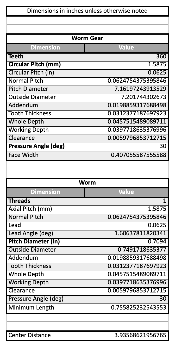
To make modeling and fabrication easier, I wrote an Excel spreadsheet containing most of these worm gear equations. In order to get it working, you must specify the values in bold (as these are the parameters from which everything else can be determined).
Since I'm using a tap with 16 threads per inch, I inputted as the circular pitch. The reason I mixed metric and imperial units in one place is because, at the time, I was trying to get as close to a pitch of 1.5mm (which many others have successfully used).
Next, I selected 360 gear teeth because this results in a conveniently sized worm gear with a ~7" diameter and simultaneously provides enough teeth to smooth out irregularities. Then, I opened up a manufacturer's CAD file modeling the matching threaded rod I'm using as the worm and found that it has a pitch diameter of 0.7094".
Finally, a pressure angle of matched my tap best (though is standard), and almost every worm I've seen on an astrophotography mount only has a single helical thread. With that, all of our bold parameters have been set :).

Conclusion
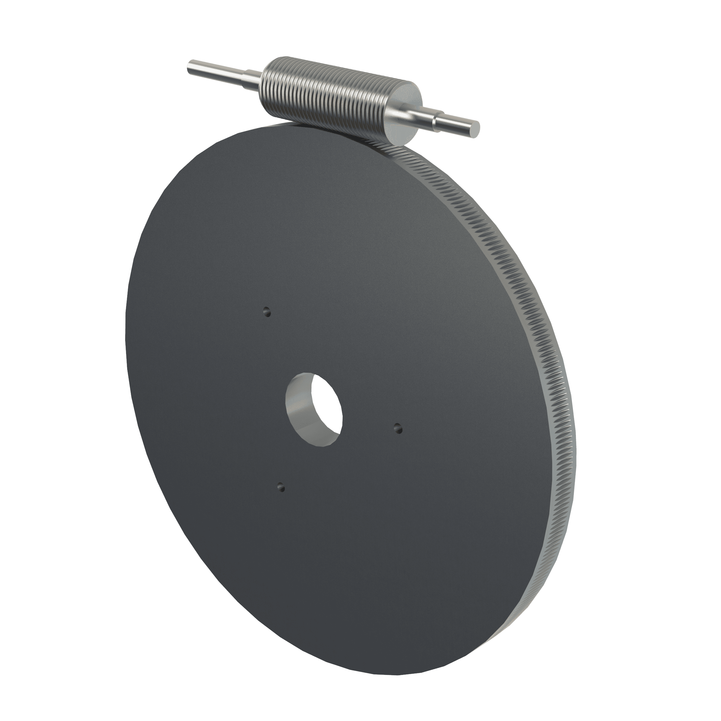
Equipped with these calculations, you should hopefully have everything you need to design a set of worm gears in CAD software. Below is a proof-of-concept that I created in SolidWorks before attempting to machine the gears in real life.
